Accurately represent the unsteady flow field around a generic main landing gear model using CFD
Determine far field noise levels caused by the different landing gear configurations
Investigate the effect of bogie inclination angle on the unsteady flow field and noise production
Grid quality determines accuracy of CFD results
Hybrid grid of 8 million cells
5.5 million structured cells in the important flow region close to the geometry
2.5 million unstructured cells further away from the model to avoid excessive grid size

Surface mesh detail
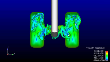
Unsteady flow field horizontal
Iso surface of vorticity coloured by velocity magnitude

Looking upstream

Looking downstream
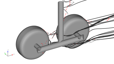
Vortex cores have been extracted using parallel vectors criterion
Four vortices are formed behind front wheel of which two are trapped on the inside of the rear wheel
Recirculation zone behind strut

Vortex cores (red) in the mean flow, rotational motion shown by seeding streamlines from vortex cores
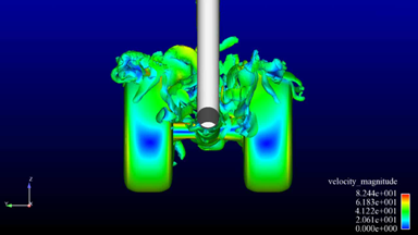
Unsteady flow field toe up
Iso surface of vorticity coloured by velocity magnitude

Looking upstream

Looking downstream
Flow separates from the top of the front wheel
Two strong vortices are formed behind front wheel and move over the top of the rear wheel
Recirculation zone behind strut

Vortex cores (red) in the mean flow, rotational motion shown by seeding streamlines from vortex cores
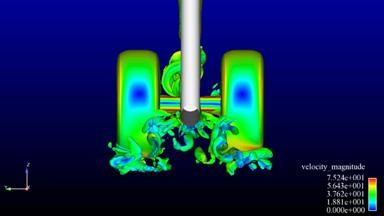
Unsteady flow field toe down
Iso surface of vorticity coloured by velocity magnitude

Looking upstream

Looking downstream
Bogie inclination angle determines where the flow separates from the front wheels
Separated flow from the front wheels forms strong vortices
There is a clear relationship between the vortex location and far field noise levels
Horizontal configuration leads to strong vortices close to the geometry and the highest noise levels
Toe down configuration leads to the greatest distance between vortices and geometry and the lowest noise levels